Compliance Distances for
2m/70cm Band Collinear Arrays
Peter DeNeef, AE7PD
In a collinear array multiple radiating elements are aligned in a combination that increases the gain. Vertical collinear antennas can be mounted in a variety of locations on a mast or a rooftop. Table 1 shows two popular configurations of “white stick” 2m/70cm band antennas. All of the internal elements listed in the table are 5/8 wave monopoles, except the 2 meter band half-wave dipole in the 1.3 m antenna. Both antennas have ground-plane radials at the base. The gain figures in the table are from [1].
Table 1. 2m / 70cm collinear arrays.
Length Elements Gain (dBi)
1.3 m 2m: One half-wave dipole 3.0
70 cm: Two 5/8 wave monopoles 6.0
2.5 m 2m: Two 5/8 wave monopoles 6.5
70 cm: Four 5/8 wave monopoles 8.0
The easiest way to estimate compliance distances (minimum permissible separation) for these antennas is to use an online calculator from the RSGB [1] or the ARRL [2]. They use the same formula, but depending on frequency the results can be different because the ARRL calculator uses FCC RF exposure limits [3], and the RSGB calculator uses 2020 ICNIRP limits [4]. For the 2m band, FCC and ICNIRP 2020 limits are the same. For the 70 cm band, FCC limits are different from ICNIRP limits.
Table 2 is a comparison of compliance limits for a 1.3 m collinear array described in Table 1. These distances are for uncontrolled areas that apply to the general public. The average power is 50 W, and ground reflections are included. The distances for the
2 m band are the same. On the 70 cm band the ICNIRP distance (4.3 m) is greater than the FCC distance (3.7 m).
Table 2. Comparison of ICNIRP and FCC compliance distances (meters) for a
1.3 m collinear array at P = 50 W.
Band ICNIRP 2020 FCC
2 m 3.2 m 3.2 m
70 cm 4.3 m 3.7 m
A simple far field formula is used in these calculators. The results are usually sufficient to show that an antenna is in compliance. If the conservative estimate from a calculator is greater than the available space, you can use a smaller, more accurate estimate from a computer simulation. For this article I used simulations to find compliance distance reduction factors for 2m/70cm band vertical collinear arrays. To use a reduction factor, multiply it times the result from the online calculator.
Near Field Calculations
Figure 1 shows results from my simulation of the of the total E-field near a 1.3 m vertical collinear array when the average power is 50 W at 145 MHz. The height above ground is 4 m, measured to the plane of the radials. Fig. 1 is a vertical slice through the cylindrically symmetric radiative near field. The yellow area shows locations where the total E-field is above the maximum permitted exposure level at 145 MHz, as specified in the FCC and the 2020 ICNIRP reference levels of whole body average exposure for the general public [3,4].
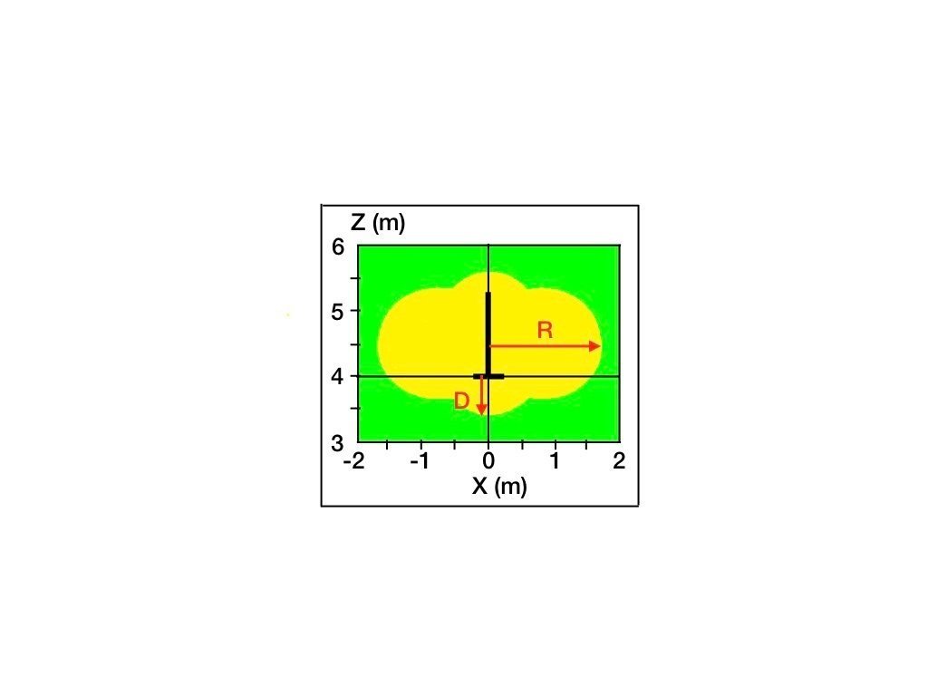
Figure 1. Simulated E-field distribution near a 1.3 m array with height = 4 m and P = 50 W at
145 MHz. The yellow area shows the region where E is above the maximum permitted exposure.
You can use the distances D and R from the figure as conservative compliance distances. The same type of approximation is used in the calculators, where the power density at a point near an antenna is compared to a maximum permitted exposure (MPE) limit. The distance where the power density equals the MPE limit is used as the compliance distance.
To estimate compliance distances for an average power P (W) and antenna height
h (m) I compare a scan of the E-field with a scan of the H-field and select the larger distance for each of the two dimensions, D and R. For the example in Fig.1, Dsim = 0.6 m and Rsim = 1.7 m. The EMF calculators give Dcalc =3.2 m (Table 2). This is longer than the simulation results because the formula is based on a model where all the radiation comes from a single point on the antenna, leading to higher estimates of the local field levels.
Relative to Dcalc the distance factors are Dsim / Dcalc = 0.19 below the array and Dcalc = 0.53 beside the array. Table 3 shows general distance factors with the 1.3 m and 2.5 m collinear arrays. These are the most conservative results (largest distances) from numerous simulations with h ≥ 2 m and P ≤ 200 W. To calculate a reduced compliance distance, multiply the distance factor from Table 3 times a compliance distance from the EMF calculator. These results are based on ICNIRP 2020 limits. With FCC limits only the 2 m band reduction factors in Table 3 are correct.
Table 3. Compliance distance reduction factors for collinear arrays with h ≥ 2m and
P ≤ 200 W. Multiply a factor from the table times a compliance distance computed by the RSGB/Ofcom EMF Calculator. For the ARRL calculator, FCC limits apply and only reduction factors for the 2 m band can be used.
1.3 m Antenna 2.5 m Antenna
Band Below Beside Below Beside
2 m 0.33 0.67 0.14 0.49
70 cm 0.35* 0.63* 0.19* 0.55*
*ICNIRP limits only
Examples
The following examples are for a 1.3 m array transmitting P = 50 W at 145 MHz and a standardized 1.8 m tall adult:
1. The minimum antenna height at which there is no exclusion zone for persons standing on the ground is hmin = Dsim + 1.8 m = (Dsim / Dcalc) * Dcalc + 1.8m. From Table 3, Dsim / Dcalc = 0.33, and hmin = (0.33 * 3.2 + 1.8) = 2.9 m. (The factor from the table is greater than 0.19 from Fig.1 because the table allows for different antenna heights
h ≥ 2m and different levels P ≤ 200 W.)
2. When h < hmin, the RSGB EMF calculator computes the horizontal separation required to maintain the compliance distance Dcalc. The smaller Dsim can not be used to calculate a horizontal separation distance because it is measured as a vertical distance.
3. For a roof-mounted array measure the height of the antenna above the floor of a living area. When h > hmin = Dsim + 1.8 m, compliance is demonstrated.
4. For areas adjacent to the antenna, the minimum horizontal distance from the antenna is Rsim = (Rsim / Dcalc) * Dcalc. For this example, Rsim = (0.67 * 3.2) = 2.1 m. This applies to points of exposure at any height above ground. As it is a horizontal distance, Rsim is less restrictive when the height of the point of exposure is similar to the antenna height. When there is a height difference, compare a second horizontal compliance distance using using Dcalc as the diagonal distance between the point of exposure and the closest point on the antenna. In that case the horizontal separation can be less than Rsim.
Simulation Models
Circuit details for the commercial antennas described in Table 1 are proprietary, but the design principle for collinear arrays is well known: In-phase areas of radiation along the antenna combine to give collinear gain in the far field. I used 4nec2 [5] to simulate the radiating areas described in the table. The ground is rich soil (relative dielectric
constant = 20 and conductivity = 0.0303 S/m), simulated with a Sommerfeld model. Validation checks with NEC v5.0 agree closely with the calculations [6].
Websearch
[1] https://rsgb.org/main/technical/emc/emf-exposure/
[2] http://arrl.org/rf-exposure-calculator
[3] https://transition.fcc.gov/bureaus/oet/info/documents/bulletins/oet65/oet65.pdf
[4] https://www.icnirp.org/cms/upload/publications/ICNIRPrfgdl2020.pdf
[5] https://www.qsl.net/4nec2/
[6] https://eznec.com/xLLNL_info.htm
Author Information
Peter DeNeef, AE7PD, is an Extra Class amateur radio operator in the USA. This website has no ads or conflicts of interest.
Email: HamRadioAndVision@gmail.com
HamRadioAndVision RF Exposure Index
HamRadioAndVision Contents Page
2/24/22